IoT Doorbell

The three parts are all complete, it’s in place and working now.

Have some photos:

Development

This is the rig used to flash the ESP12.

Photo of the rig used to flash the ESP12

ESP12 with jumper leads

Chime

This now lives in my shed, powered by an external HDD which has a USB port.

ESP12 doorbell chime

Doorbell

This lives under the sofa so it’s audible in the living room and triggers other chimes.

IoT Doorbell Master

IoT Doorbell: The Doorbell

I already have a wireless doorbell which has two ringers, one is mains which I’m not prepared to mess with, and the other is battery powered so I’m happy to fiddle.

Rather than buying an inexpensive wifi module and reading the wifi signal from the doorbell itself I’m going to read the speaker +ve so that I know when it’s actually dinging.
I’m hoping to be able to slip an ESP12 (and voltage converter) into the small doorbell ringer, and power it from USB instead of battery.

Continue reading

IoT Doorbell: The Server

I need a server to be the central point of communications to and from the ESP12s. I have a single bay QNAP NAS box which has a web server on it which does the trick nicely.

I’m using MySQL and PHP, both of which are installed on the NAS box.

At the moment I have two pages. One called register.php which devices use to register themselves, and another called doorbell.php which sets the chimes off.

There’s a simple SQL table which has MAC (key), IP, name and a timestamp of when it was added.

Continue reading

IoT Doorbell: The Chime

My first ESP8266 project is to extend the wireless doorbells we have. The idea is that I’ll hack the portable unit to make it run from USB and add in wifi capability so that when the doorbell is pressed it’ll tell the network.

This project has three parts: the server, the chime, the doorbell.

This post is about the chime.

The Chime

Continue reading

ESP8266

I’ve started playing with ESP-12s.  I have a NodeMCU development board and three ESP8266MOD (ESP-12) boards.

I’m using the arduino IDE to program, which makes it super easy.  The only difficulty I’ve faced so far is getting the ESP12s to run after flashing.

This is a quick summary in case I need to refer to it again later:

Flashing

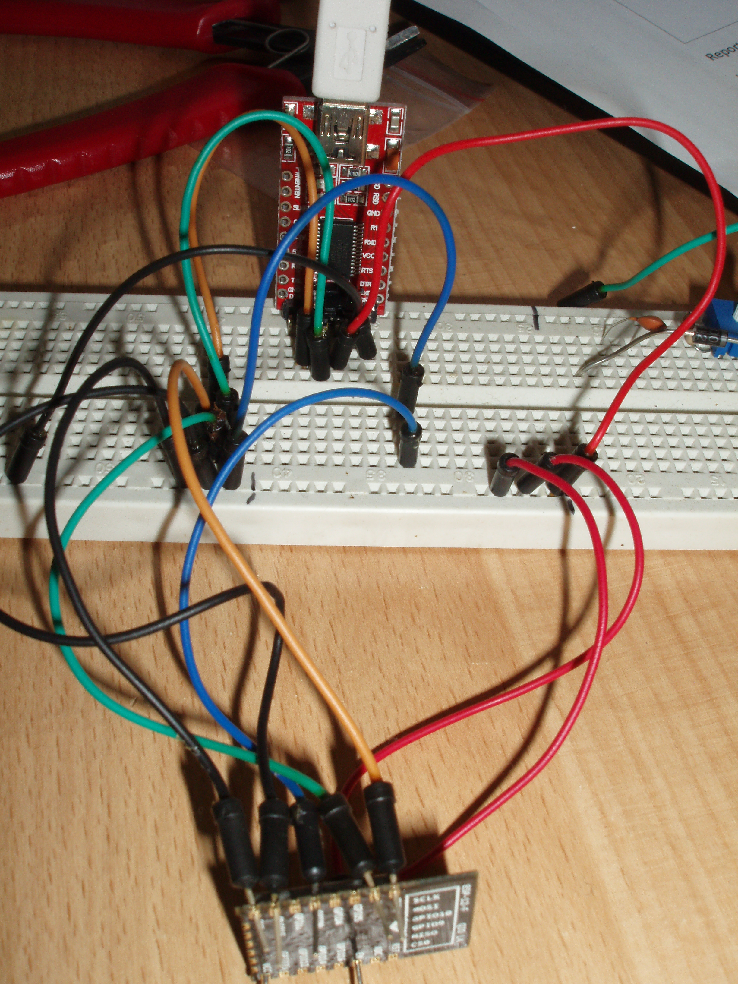
To flash, you need to wire it up like this:
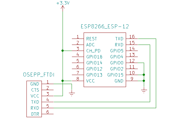
[stolen from here]

I thought this would involve solder but it doesn’t – jumper wires through the holes works fine. Single core wire is slightly better as you can bend the end round to prevent it falling out.
With that wiring there’s no faffing with a reset button, it boots straight into upload mode.

Running

This is where I came unstuck and it took me a while to figure this out:

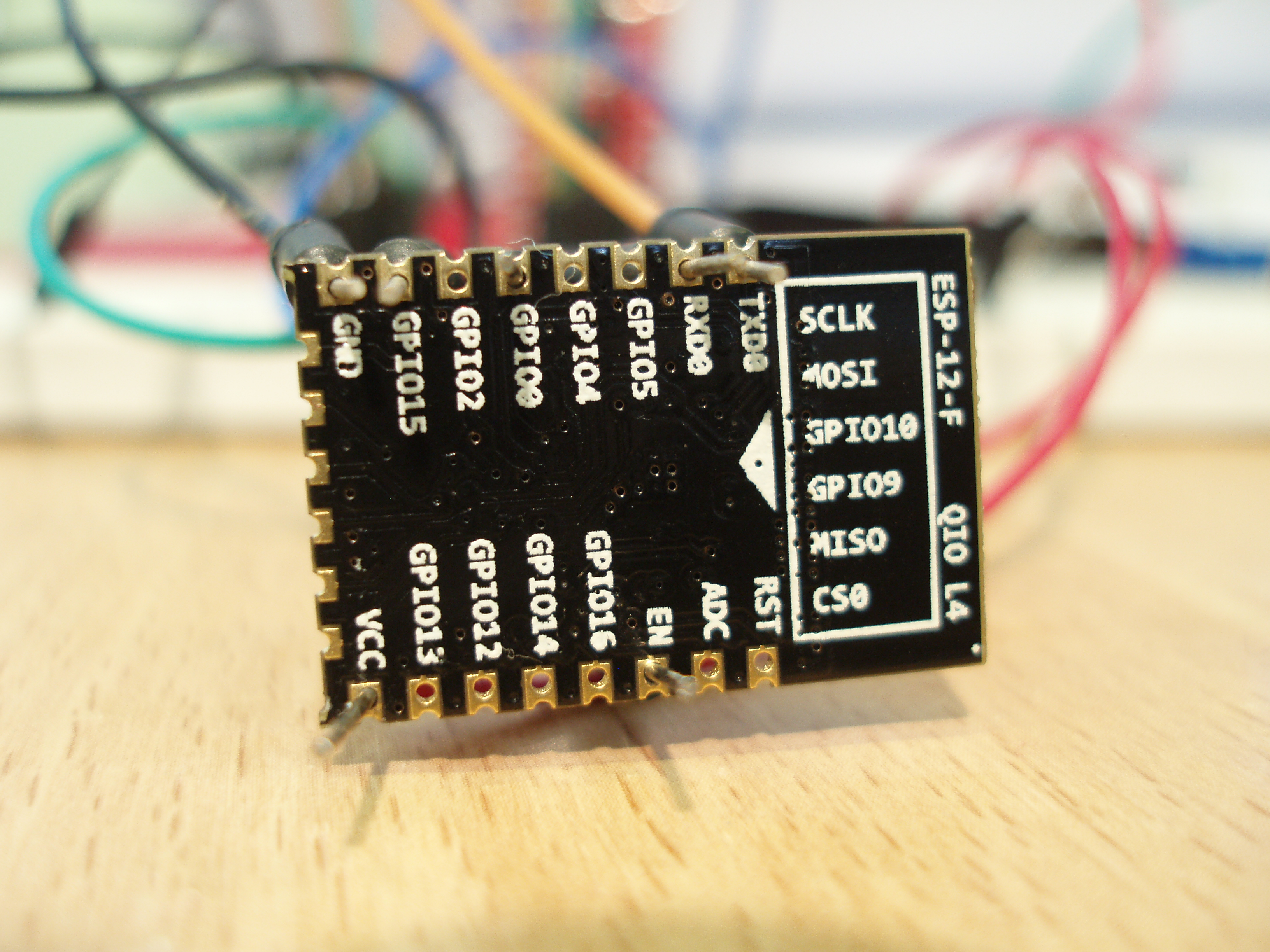
  • EN (marked CH_PD above) needs to stay pulled up to 3.3v.
  • GPIO0 needs pulling up to 3.3v via a 10k resistor.
  • GPIO15 needs to be pulled to ground (leave it as it is).
  • TXD and RXD can come out.